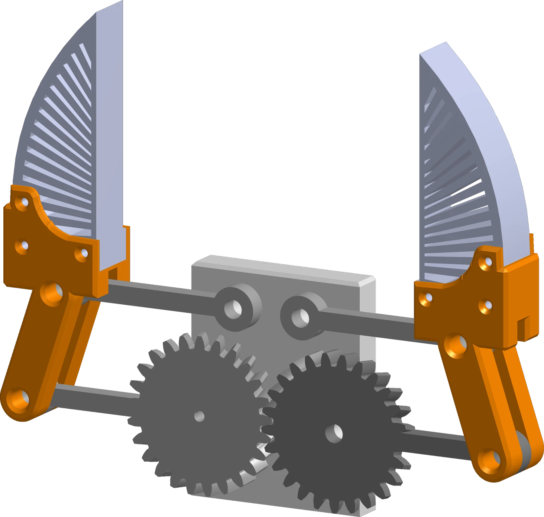
A claw that closes straight
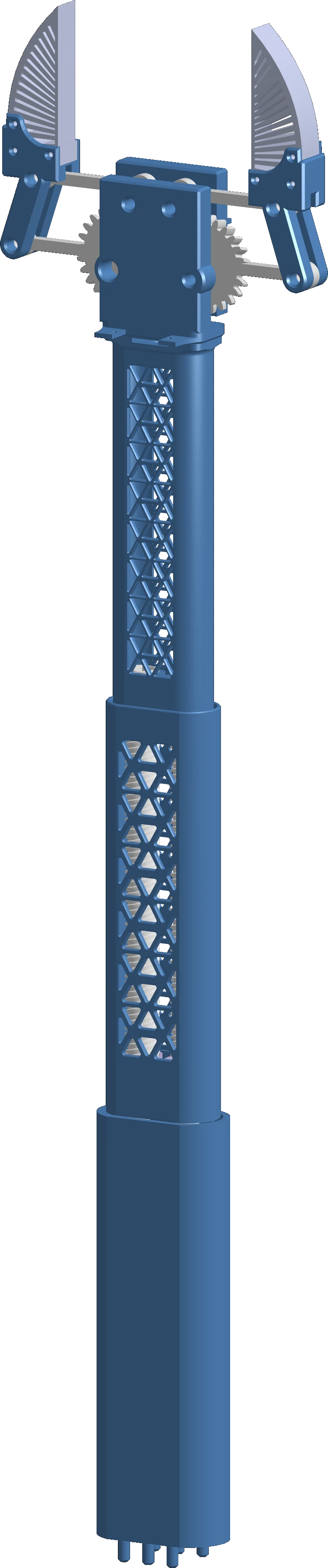
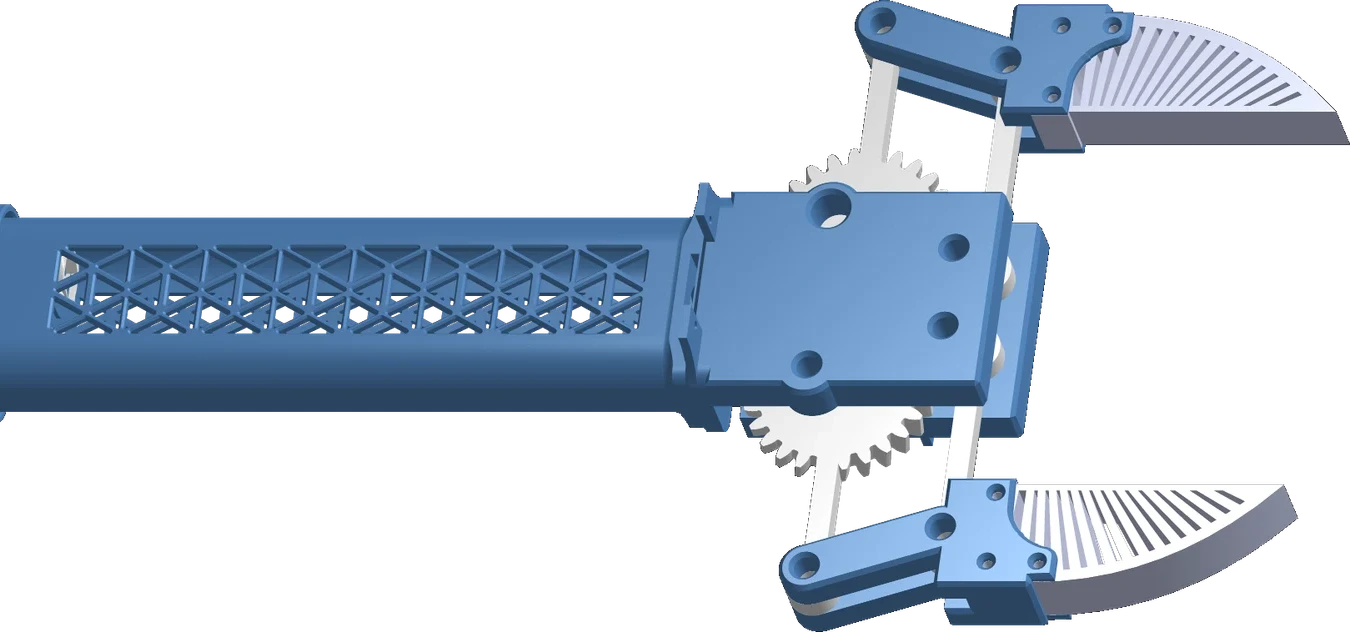
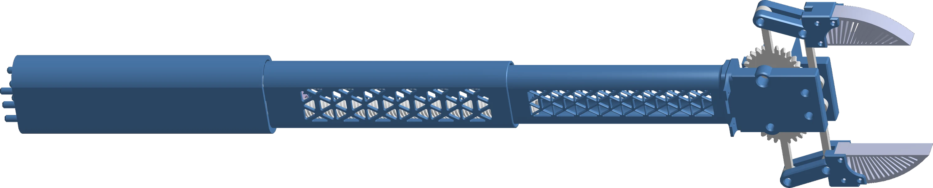
A four-bar linkage moves the fingers in a straight line, and Fin Ray fingers bend to wrap around whatever they hold.

A motorized telescoping grabber for seniors, designed and built by four students for Project Invent.
Falling is the leading cause of injury-related death and loss of independence for seniors. A dropped pill bottle or a TV remote on the floor should not be a risk.
Reaching the floor shifts balance forward, right where most falls start.
One fall can mean a hospital stay and the end of living alone.
Arthritis makes the hard squeeze of a store-bought reacher painful or impossible.
“Our residents and clients, they’re losing strength or arthritis is crippling their hands, so being able to just push a button and have it help them enables them to have that independence longer.”


In November 2025, Project Invent paired our team with Mozaic Senior Life and asked one question: what makes daily life harder for their residents? We filled a page with ideas, from a signature tablet to a two-size robot hand.
The one that stuck was a cane that also works as a grabber, something that could stop a fall when picking things up and even help pull up the covers at night.
Over the next six months that idea became Reach: a tool that extends on its own, so the user never has to bend, stretch or squeeze.
Every milestone below comes from the weekly design log and the Onshape model’s history.
A list of ideas for senior living: a secure signing tablet, a hybrid walker and grabber, a robot hand, a cane that retracts.
The team commits to a cane that doubles as a grabber and asks Mozaic for a follow-up meeting and quotes.
The Onshape document named REACH is created. It will grow to more than thirty part studios and assemblies.
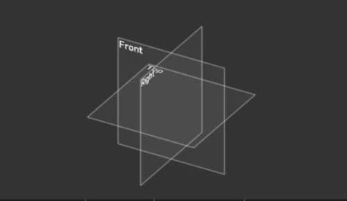
Two lead screws threaded at 0.18 in pitch. Onshape cannot simulate the overlapping constraints, but the concept holds.
 Simulation failed
Printed lead screw A, lead screw B and connector C. The spline tip and thread tolerances were off, and B would not seat.
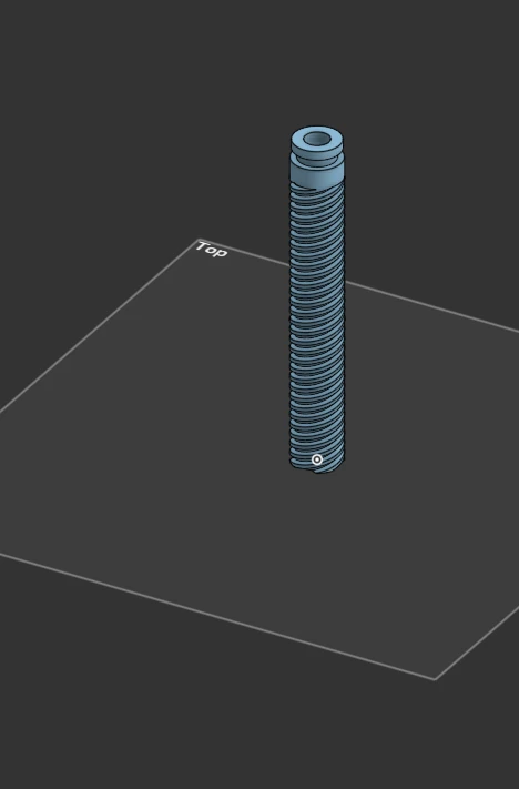 Did not fit
Tolerance tests set a 1.5 mm thread offset and a 0.5 mm hex fit. The clear and white prototype extends exactly as planned.
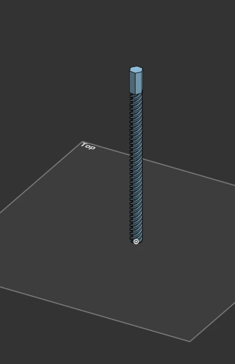 Worked
Lead screw A grows to 203 mm at 2.54 mm pitch, with a 3 mm channel for wires and six global variables driving the design.
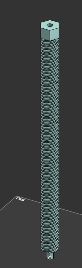
Connector AB needs a smooth bearing for lead screw B. A switch from the Dremel to a Prusa printer means every tolerance is retested. Roller bearings keep failing.
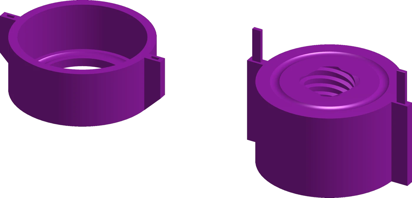 Too much friction
The anti-rotation wings on the connector poke through the outer shell, creating pinch points for fingers. Version 0.0 is retired.
RetiredMid-rebuild idea: run two parallel lead screws. The connectors cannot spin, the wings disappear, and wires pass through the center. This becomes version 0.2.

Connector V2 comes out slimmer and lighter, and 3 mm steel bearing balls are ordered.
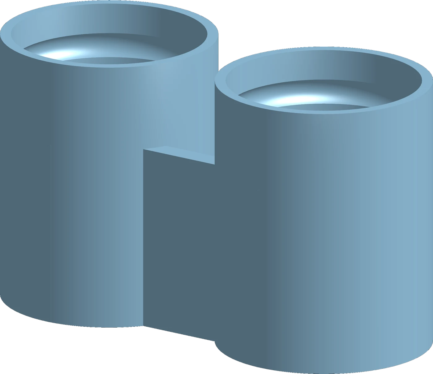
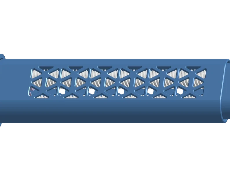
Each stage-two lead screw gets its own bearing race and a cage for the steel balls. Stage three becomes a simple threaded tube, and the wires route through a 7.5 mm gap and an 8 mm channel.
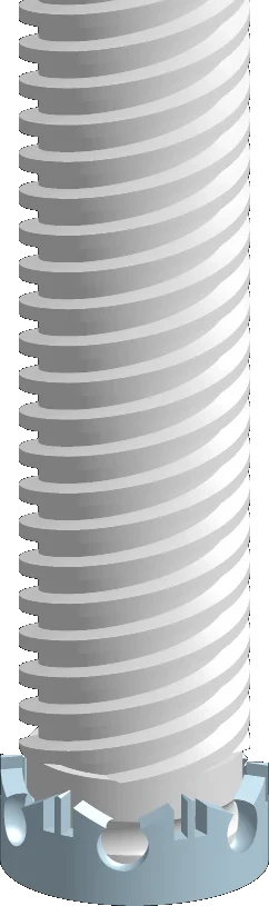
Printed in PETG with five perimeters. With the steel balls in, Connector AB turns smoothly and holds lead screw B in place. The claw design begins.
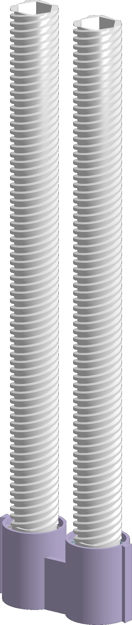 Worked
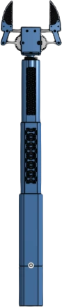
Handle, three telescoping stages and the claw come together in one model.
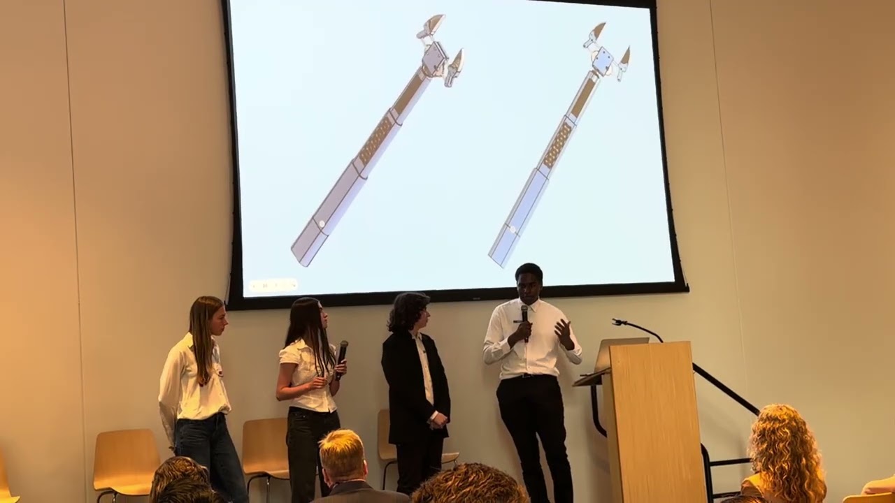
Team SO-lutions presents Reach at Project Invent and wins the Product Pivot award.
AwardRefining the handle, the stage-two sleeves and stage three so Reach can go to residents at the senior living home.
A four-bar linkage moves the fingers in a straight line, and Fin Ray fingers bend to wrap around whatever they hold.
Two threads per connector stop it from spinning and leave a channel in the middle for wires.
2.54 mm
Four-start ACME threads, so each turn of a lead screw moves its stage 10.16 mm.
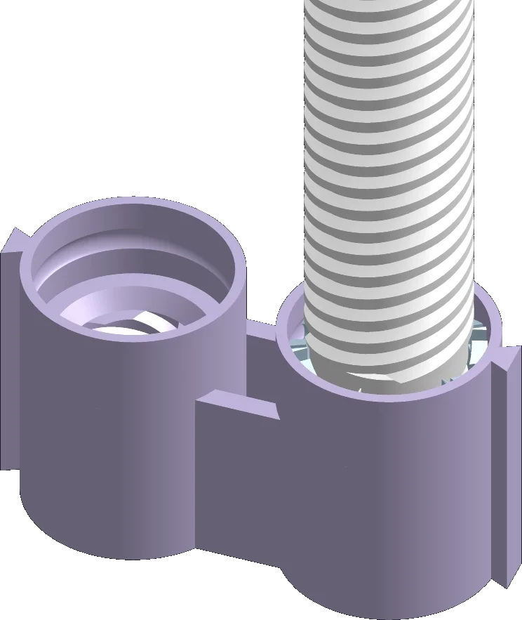
3 mm
The base of each stage-two lead screw is a bearing race. Balls in the cage roll against the outer race in the AB connector, so the screw spins freely but cannot pull out.
PETG, five perimeters, gyroid infill and organic supports, tuned after weeks of tolerance tests on two printers.
At Project Invent, Reach won the Product Pivot award. Watch the full pitch and the moment we found out.

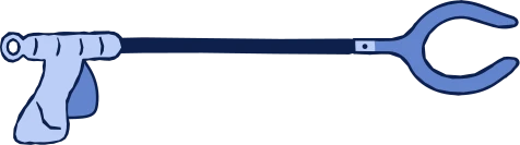
The usual reacher is a fixed-length stick with a trigger you squeeze hard. Reach adjusts its own length and closes with a button, so grip strength stops being the limit.
Sources: CDC, Disability Impacts All of Us; SeniorLiving.org statistics.